pwm-procedure = PWM "(" identifier [ "," pin-number ] "," duty-expression ")" .
This is a poor man's DAC function, based on the PBASIC function (Basic Stamp®). It permits to output a series of pulses to a pin that will give a mean voltage proportional to the given <duty>.
There's two syntax possibilities:
<pin-number> is a constant expression giving a value in a range of 0 to 7.
<duty-expression> is an expression giving a BYTE range.
The implemented mechanism is:
If an RC is wired to the pin, the capacitor will hold the mean voltage value, so it makes an easy and cheap 8-bit DAC function.
Several PWM statements may be necessary to charge the capacitor, depending on the RC value.
The algorithm is not a simple PWM as HW ones; it makes always 256 loops and interleaves 1 and 0 as needed at a variable frequency. For example, a duty value of 128 will produce 128 pairs of 1 and 0.
The theoretical voltage value is never achieved, it depends on the pin and mostly on the device; typical 1 is Vdd-0.7V and typical 0 is Vss+ε.
The theoretical LSB error is 1/256 or 0.4%.
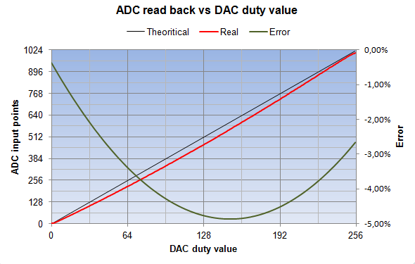
Unfortunately, as the routine is very short and simple to be fast, there's some linearity problems; the error curve below shows a form factor depending on something like k.(Duty - 128)², with a slight shift probably due to the PIC hardware. This linearity may be acceptable, else some correction has to be used.
The curves below show one real world case made with a PIC measuring the voltage on the capacitor with its own 10-bit ADC (with Vref = Vss-Vdd), just after executing enough PWM calls to stabilize the voltage: